







Introduction
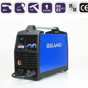
If your MIG 205GDM (230V) displays the EU.02.01 error during welding, don’t assume the machine is faulty.
In most cases, this error is not caused by the power source itself, but by excessive load in the wire feeding system, especially when using flux-cored welding wire.
This article summarizes our field troubleshooting experience and explains the most common causes, diagnostic procedures, and solutions.
What Does EU.02.01 Mean?
According to our technical team,
EU.02.01 indicates overvoltage protection in the auxiliary power supply system.
Although the alarm points to the auxiliary power circuit, the actual trigger is often an abnormal load from the wire feeder motor.
When the feeder encounters excessive resistance, the motor current increases, causing the control system to enter protection mode.
Step 1. Determine Whether the Machine Is Actually Faulty
Before replacing any parts, perform this simple test.
Test Procedure
Disconnect the welding wire.
Keep the MIG torch connected.
Press the torch trigger.
Result
If:
- the machine powers normally
- the wire feeder motor runs normally
- no EU.02.01 error appears
then the power source is generally functioning correctly.
The problem is most likely located in the wire feeding system rather than the inverter.
Step 2. Check the Wire Feeding System
This is the most common source of the problem.
Inspect the following:
- Is the wire spool installed correctly?
- Is the spool brake adjusted too tightly?
- Is the wire tangled or bird-nested?
- Does the wire feed smoothly by hand?
- Is the drive roller pressure too high?
- Is the wire diameter matched with the drive roller groove?
- Is the wire liner damaged or excessively worn?
- Is the contact tip blocked?
Any additional resistance increases motor load and may trigger protection.
Step 3. Flux-Cored Wire Requires a Larger Contact Tip
One issue we frequently encounter involves 1.0 mm flux-cored wire.
Many users naturally install a 1.0 mm contact tip.
However, this is often the root cause.
Why?
Flux-cored wire contains powdered flux.
During welding:
- the wire heats rapidly
- the tubular wire expands slightly
- friction inside the contact tip increases
A 1.0 mm tip may become too tight, causing the wire to stick.
The feeder motor then attempts to push harder until protection activates.
Recommended Solution
For 1.0 mm flux-cored wire, we recommend using a 1.2 mm contact tip.
The additional clearance allows the wire to feed smoothly even after thermal expansion.
Solid welding wire generally does not expand in the same way, so a matching 1.0 mm contact tip usually works perfectly.
Why Many Manufacturers Recommend an Oversized Contact Tip
This recommendation is not unique to our machines.
Many flux-cored wire manufacturers suggest using a contact tip one size larger whenever wire jamming occurs.
Reasons include:
- manufacturing tolerance of flux-cored wire
- thermal expansion during welding
- reduced friction inside the tip
- improved feeding stability
This is considered normal industry practice.
Step 4. If Using Aluminum Wire
If you are welding aluminum,
make sure the torch uses a Teflon liner.
A standard steel liner creates excessive resistance and can easily cause feeding problems.
Always verify:
- Teflon liner installed
- correct U-groove drive roller
- appropriate contact tip
- spool gun (recommended for soft aluminum wire)
Additional Items to Inspect
Besides wire feeding, also check:
Ground Connection
Poor grounding can cause unstable arc performance.
Inspect:
- work clamp
- cable connection
- oxidation
- loose terminals
Gun Connection
Ensure:
- MIG torch connector is fully tightened
- trigger connection is secure
- no damaged pins
Contact Tip
Replace the contact tip if:
- clogged
- worn
- oversized due to wear
- damaged by burn-back
Wire Liner
Replace the liner if:
- worn
- contaminated
- kinked
- stretched too long
A damaged liner greatly increases feeding resistance.
Drive Roller Pressure
Too much pressure does not improve feeding.
Instead, it can:
- deform the wire
- create metal shavings
- accelerate liner wear
- increase motor load
Adjust only enough pressure to feed the wire without slipping.
Common MIG Feeding Problems and Solutions
| Problem | Possible Cause | Recommended Solution |
|---|---|---|
| Wire bird nesting | Excessive drive roller tension | Reduce roller pressure |
| Wire burns back | Wrong contact tip | Install correct tip |
| Poor penetration | Wrong wire size or poor grounding | Check wire and ground clamp |
| No wire feed | Drive roller not engaged | Adjust tension |
| No arc | Loose gun or ground connection | Tighten all connections |
| EU.02.01 error | Excessive feeder load | Inspect complete wire feeding system |
Preventive Maintenance Tips
To reduce future feeding problems:
- Keep welding wire clean and dry.
- Replace worn contact tips regularly.
- Replace liners periodically.
- Use the correct drive roller.
- Avoid overtightening the spool brake.
- Match wire diameter with the proper contact tip.
- Clean the nozzle frequently.
- Check ground connections before welding.
Conclusion
In our service experience, EU.02.01 on the MIG 205GDM (230V) is usually not an inverter failure.
Instead, it is most commonly related to excessive resistance in the wire feeding system.
The most frequent causes include:
- Incorrect contact tip size
- Flux-cored wire expansion
- Wire liner resistance
- Bird nesting
- Excessive drive roller tension
- Spool brake too tight
- Improper wire installation
Systematically checking these items can resolve the majority of cases without replacing electronic components.